 HALDA RALLY COMPUTER
HALDA RALLY COMPUTER E
HALDA ROAD COMPUTER
Users Manual
HALDA RALLY COMPUTERUsers Manual
| The Halda Road Computer and Halda Rally Computer e should be installed by a qualified mechanic. |
Make the necessary connections in accordance with the wiring diagram below. NOTE that there are two alternative connection systems. The system used will depend on whether the vehicle is equipped with a master switch for the electrical system or not. The latter alternative is the most common.
Before commencing to fit a Halda Road Computer or Halda Rally Computer e you must check that your Halda Computer runs on the same voltage as the car's electrical system. A label on the power unit states whether your Halda Computer is designed for a 12V or 24V system with negative earth.
The red wire supplies the electronic circuitry with current from the positive terminal of the battery. Connect it to one of the car fuses that is always live.
The green wire supplies the control panel display with current. Connect it to a fuse that is live only when the ignition is switched on.
Connect the black wire to a suitable earthing point. In the alternative with a master switch for the electrical system, connect the black wire to the negative terminal of the battery.
|
Two versions of the Halda Road Computer and Halda Rally Computer e are available. One for cars with a mechanical speedometer and drive cable and one for cars with an electronic speedometer and electric leads. The latter version requires a circuit board to be fitted in the power unit before it is mounted in place. See Electronic Speedometer Installation Diagram.
Pulse generators with different connecting threads, square drivers and snap-on couplings are available for different car makes and models. Check that you have the right mounting kit before starting to install your Halda computer.
Fit the control panel with its adjustable brackets where the displays can be easily read and where the various keys and buttons are within easy reach. Give a thought to the danger of injury in an accident when deciding where to mount the control panel.
A suitable place to mount the power unit is out of the way under the vehicle instrument panel. However, the sliding cover on the unit should be accessible for changing the battery and operating the switch.
Mechanical Speedometer Installation Diagram
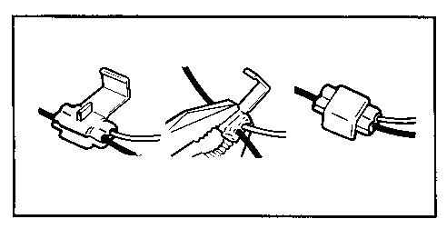
Disconnect the speedometer cable (5) from the speedometer (1). Using a suitable square drive (3), mount the pulse generator (2) on to the speedometer in place of the speedometer cable.
If the space behind the speedometer is limited, an extension cable (4) with square drive can be fitted between the speedometer and the pulse generator. See Table 1 for suitable extension cables.
Connect the speedometer cable (5) to the pulse generator.
Connect the pulse generator lead (6) to the pulse generator. Note that the pulse generator connector (7) is not symmetrical. Fit the connector so that its black shoulder (8) enters the space (9) at the side of the other connector.
Note that the contacts in the pulse generator connector are mounted on ceramic insulating material which does not withstand bending.
When the two connectors are fitted firmly together, the nut (10) can be tightened finger-tight.
Plug the pulse generator lead into the matching socket on the short side of the power unit (11). Connect the ribbon cable (12), which runs between the control panel and the power unit, to the connector (13) underneath the sliding cover on the power unit. Fit the backup battery in place.
Turn the switch (16) to the On position and your Halda Road Computer or Halda Rally Computer e is ready for calibration.
Electronic Speedometer Installation Diagram
Begin by mounting a circuit board (1) in the power unit (2).
Unscrew the end plate (3) on the short side of the power unit where the row of sockets are located. Remove the panel (4) and sliding cover (5).
Remove the three short-circuiting jumpers (6) and slide the circuit board (1) into the slot so that the previously short-circuited pins make contact with the new circuit board. Fit the power unit panel (4), sliding cover (5) and a new end plate (3) in place.
Mount the power unit (2) in the car and connect the ribbon cable (7) to the connector (8) underneath the sliding cover. Fit a backup battery (10) in place.
Connect the pulse generator connector (11) to the connector sleeve (12). Note that the pulse generator connector (11) is not symmetrical. Fit the connector so that its black shoulder (13) enters the space (14) at the side of the connector in the connecting sleeve.
When the two connectors are fitted firmly together, the nut (10) can be tightened finger-tight.
One brown wire and one white wire extend from the connecting sleeve. Refer to electronic speedometer table for connection for your car. Using two splicing clamps (15), connect these wires to the speedometer wires. To ensure reliable connection, the cross-section area of the speedometer wires should not be less than 0.3 mm2, which corresponds to a diameter of 0.6 mm and an outside diameter, including insulation, of about 1.6 mm.
Position the unstripped wires between the clamps and close the clamps with a pair of pliers. Snap the cover in place.
 |
Good contact between the pulse generator wires and the speedometer wires is easily obtained by means of the splicing clamps. |
Turn the switch (16) to the On position and your Halda Road Computer or Halda Rally Computer e is ready for calibration.
Garphyttan Haldex AB allows a guarantee of one full year on manufacturing defects.
The defective product shall be immediately returned to the dealer, who will forward it to Garphyttan Haldex AB for repair or replacement with a new unit.
Costs of transportation to be paid by the customer.
A Halda Road Computer or Halda Rally Computer e does not normally require service of any kind.
The backup battery normally requires changing once a year.
In the event of any fault you should take your Halda Road Computer or Halda Rally Computer e to a service workshop authorized by Halda or return it to Garphyttan Haldex AB, Box 250, S-301 04 Halmstad, Sweden.
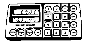
The instrument has two displays.
The top display shows:
-- distance counter 1 and 2
-- calibration number
-- entered numerical values before they are transferred to distance counter or clock
The bottom display shows:
-- distance counter 3
-- clock
On the displays there are also function indicators which indicate what is shown on the displays and the operating modes for the instrument.
Example
![]()
![]()
In this example distance counter 1 is shown on the top display (889.75 km) and the clock on the bottom display (1 h 22 min 53 sec). The mode indicators show that distance counters 1 and 3 are counting up, distance counter 2 is counting down and that the clock has stopped counting.
The keyboard has 20 keys in four different colours:
--blue
--red
--brown
--green
The different colours indicate different kinds of use for the keys.
Blue keys -


 these keys are used to show the different functions on the display.


 this key is used to change the intensity level of the displays.
Red keys -
These keys are used together with
to
 program the corresponding function to count up
 program the corresponding function to count down
 stop the counting at the corresponding function
Brown keys -
 -
-
 these keys are used together with
to enter figures into the corresponding function.
To enter 0 use
Green keys -
 This key is used to clear display 1 during or immediately after a numerical entry, to turn off the alarm and together with
to reset the corresponding function.
 This key is an instant reset for distance counter 1.
The instrument has an alarm-signal which sounds when any of the distance counters or the clock pass zero.
The alarm also indicates that the CLR-1 function has been used. Thereby the co-driver gets indication that distance counter 1 is reset. This is useful specially when using the remote control (optional).
![]() To count up on distance counter 1
To count up on distance counter 1
![]() enter
enter
![]() To count down on distance counter 2
To count down on distance counter 2
![]() enter
enter
![]() To stop counting on distance counter 3
To stop counting on distance counter 3
![]() enter
enter
The clock is handled the same way.
To preset the distance counter 2 to 5.50 km (assuming that the counter is reset -- see "Resetting distance counters and clock")
![]() enter
enter
![]()

To preset the clock to 1 h 30 min 0 sec
enter

![]()
![]() alternatively
alternatively
To add 2 min 30 sec to the clock (assuming that the clock has the value of 1 h 30 min 0 sec immediately before the addition)
![]() enter
enter
![]()

To subtract 0.45 km from distance counter 1 (assuming that distance counter 1 has the value of 22.38 km immediately before the subtraction)
![]() enter
enter
![]()

To reset distance counter 3
![]() enter
enter
![]()
To avoid unintended resetting has to be pressed within 1.5 sec after is released.
There is also a possibility to reset distance counter 1 directly.
![]() enter
enter
![]()
If distance counter 1 is in count mode counting starts again when is released.
This function can also be remote controlled (optional).
When entering the display shows the last entered calibration number.
![]() Example: Calibration number 5.67
Example: Calibration number 5.67
![]()
If the calibration number is to be changed, the new number is entered on the keypad and is shown on the display.
![]() Example: New calibration number 5.01
Example: New calibration number 5.01
![]()
If the new calibration number is unknown proceed as follows:
![]() A. Drive to the start point of a known distance, stop the car and enter
A. Drive to the start point of a known distance, stop the car and enter
![]()
![]() B. Enter
B. Enter
![]()
![]() C. Drive to the end of the known distance and stop the car.
C. Drive to the end of the known distance and stop the car.
![]() The display shows for example:
The display shows for example:
D. From the value now shown on display 1 the calibration number is calculated by using the formula:
                                         100
                Calibration number = ----------- X measured distance (miles or km)
                                     Shown value
Example: If the measured distance is 1.00 km and the shown value is 19.98 you get:
                                               100
                         calibration number = ----- X 1.00 = 5.005
                                              19.98
which is truncated 5.01.
The calibration number can now be entered as previously described.
Calibration numbers between 0.01 and 99.99 can be used.